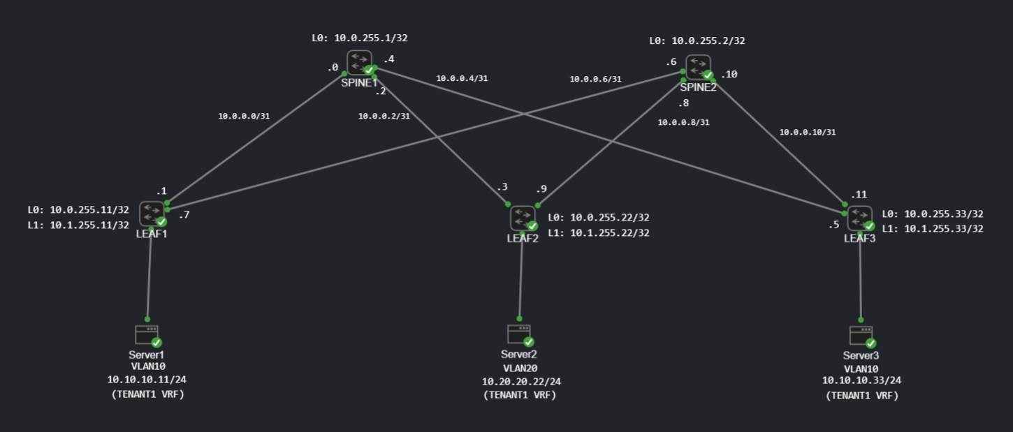
The lab fabric: two route-reflector spines, three VTEP leaves and one server attached to each leaf.
What I built
I am currently studying VXLAN-EVPN and have now built my first lab.
The topology uses two spines and three leaves:
- SPINE1 and SPINE2 provide redundant underlay paths and act as EVPN route reflectors.
- LEAF1 and LEAF3 extend VLAN 10 across L2VNI 10010.
- LEAF2 hosts VLAN 20 in L2VNI 10020.
- All three leaves share the
TENANT1VRF through L3VNI 50000. - Server1 and Server3 use the VLAN 10 anycast gateway
10.10.10.1/24. - Server2 uses the VLAN 20 anycast gateway
10.20.20.1/24.
OSPF provides transport reachability, MP-BGP EVPN distributes endpoint and prefix information, and VXLAN carries the tenant traffic between VTEPs.
Underlay: OSPF for Loopback Reachability
Each leaf has a routed /31 link to each spine. OSPF area 0 advertises those links together with two loopbacks:
Loopback0is used to source the EVPN BGP sessions.Loopback1is the VTEP address used by VXLAN.
For example, LEAF1 reaches SPINE1 over a point-to-point underlay link and advertises both loopbacks into OSPF:
interface Ethernet3
   description Link to SPINE1
   no switchport
   ip address 10.0.0.1/31
   ip ospf network point-to-point
   ip ospf area 0.0.0.0

interface Loopback0
   ip address 10.0.255.11/32
   ip ospf area 0.0.0.0

interface Loopback1
   ip address 10.1.255.11/32
   ip ospf area 0.0.0.0
Loopback0 is used for identifying routers in OSPF and BGP processes, whereas Loopback1 is used as the source for all VTEPs.
Overlay: iBGP EVPN
The EVPN overlay runs in private AS 65000. Each leaf establishes iBGP EVPN sessions from Loopback0 to both spine loopbacks:
router bgp 65000
   neighbor EVPN-SPINES peer group
   neighbor EVPN-SPINES remote-as 65000
   neighbor EVPN-SPINES update-source Loopback0
   neighbor EVPN-SPINES send-community extended
   neighbor 10.0.255.1 peer group EVPN-SPINES
   neighbor 10.0.255.2 peer group EVPN-SPINES

   address-family evpn
      neighbor EVPN-SPINES activate
The leaves do not need a full mesh. Each spine reflects EVPN routes between the leaves, and the extended communities carry the route targets used to decide which services import each route.
The two reflection paths are visible in the BGP output. The same remote route arrives with cluster-list IDs 10.0.255.1 and 10.0.255.2, giving the overlay redundant control-plane paths without changing the originating VTEP next hop.
L2VNIs, Anycast Gateway and L3VNI
VLAN 10 is stretched between LEAF1 and LEAF3 using VNI 10010. Both leaves use the same virtual IP and virtual MAC, so a host sees the same default gateway regardless of which leaf it is attached to:
interface Vlan10
   vrf TENANT1
   ip address virtual 10.10.10.1/24

interface Vxlan1
   vxlan source-interface Loopback1
   vxlan udp-port 4789
   vxlan vlan 10 vni 10010
   vxlan vrf TENANT1 vni 50000

ip virtual-router mac-address 00:1c:73:00:00:99
The BGP service configuration gives the MAC-VRF its own route distinguisher and route target. The tenant VRF has a separate RD per leaf but a common import/export route target for L3VNI 50000:
router bgp 65000
   vlan 10
      rd 10.0.255.11:10010
      route-target both 65000:10010
      redistribute learned

   vrf TENANT1
      rd 10.0.255.11:50000
      route-target import evpn 65000:50000
      route-target export evpn 65000:50000
      redistribute connected
Traffic between the two VLAN 10 servers can stay within L2VNI 10010. Traffic between VLAN 10 and VLAN 20 is routed at the ingress leaf’s anycast gateway, transported across L3VNI 50000 and then delivered into the destination L2VNI. That is the symmetric IRB model: both directions use the tenant L3VNI between the ingress and egress VTEPs.
Reading the EVPN Table
The most useful part of the lab was connecting the configuration to the routes EOS actually installed. LEAF2’s EVPN table contains three route types relevant to this design.
Type 2: MAC/IP Advertisement Routes
LEAF2’s global EVPN RIB contains the remote endpoints behind LEAF1 and LEAF3, while its directly attached server appears as a local route with no BGP next hop:
RD: 10.0.255.11:10010 mac-ip 5254.000f.668e 10.10.10.11
   Next Hop 10.1.255.11

RD: 10.0.255.33:10010 mac-ip 5254.006f.0190 10.10.10.33
   Next Hop 10.1.255.33

RD: 10.0.255.22:10020 mac-ip 5254.00d7.9ccc 10.20.20.22
   Next Hop -
The next hops are VTEP loopbacks, not physical interfaces. For each remote endpoint, EOS also shows a MAC-only Type 2 route alongside the MAC/IP binding.
Type 3: IMET Routes
The IMET routes advertise VTEP membership for each L2VNI:
RD: 10.0.255.11:10010 imet 10.1.255.11
   Next Hop 10.1.255.11

RD: 10.0.255.22:10020 imet 10.1.255.22
   Next Hop -

RD: 10.0.255.33:10010 imet 10.1.255.33
   Next Hop 10.1.255.33
These routes build the membership needed for BUM handling in the VXLAN segment.
Type 5: IP Prefix Routes
The tenant subnets are also advertised as IP prefixes through L3VNI 50000:
RD: 10.0.255.11:50000 ip-prefix 10.10.10.0/24
   Next Hop 10.1.255.11

RD: 10.0.255.33:50000 ip-prefix 10.10.10.0/24
   Next Hop 10.1.255.33

RD: 10.0.255.22:50000 ip-prefix 10.20.20.0/24
   Next Hop -
LEAF1 and LEAF3 both originate 10.10.10.0/24 because they both host that anycast-gateway subnet. LEAF2 originates 10.20.20.0/24 locally.
Looking at the imported route inside TENANT1 makes the path multiplication clear:
LEAF2#show ip bgp 10.10.10.0/24 vrf TENANT1
BGP routing table entry for 10.10.10.0/24
 Paths: 4 available

  10.1.255.11 from 10.0.255.1, imported EVPN route
    Originator: 10.1.255.11, Cluster list: 10.0.255.1
    Route-Target-AS:65000:50000 Remote VNI: 50000

  10.1.255.11 from 10.0.255.2, imported EVPN route
  10.1.255.33 from 10.0.255.2, imported EVPN route
  10.1.255.33 from 10.0.255.1, imported EVPN route
There are four available control-plane paths because two VTEPs advertise the VLAN 10 prefix and both spines reflect each advertisement. The route target imports them into TENANT1, while the remote VNI confirms that routed tenant traffic uses VNI 50000.
Those four entries do not represent four different VXLAN tunnels. There are two originating VTEPs, 10.1.255.11 and 10.1.255.33, and each route is learned through two route reflectors.
No Type 1 or Type 4 routes appear because the servers are single-attached; this lab does not use EVPN multihoming or Ethernet segments.
Forwarding-Plane Verification
The EVPN routes confirm that the control plane is working. I also checked the VXLAN and tenant routing tables to confirm that EOS had programmed the forwarding state.
Remote MAC and VTEP on LEAF1
LEAF1#show vxlan address-table
          Vxlan Mac Address Table
----------------------------------------------------------------------

VLAN  Mac Address     Type      Prt  VTEP          Moves  Last Move
----  -----------     ----      ---  ----          -----  ---------
  10  5254.006f.0190  EVPN      Vx1  10.1.255.33   1      1:12:28 ago

Total Remote Mac Addresses for this criterion: 1
LEAF1 has learned Server3’s MAC through EVPN and installed it against LEAF3’s VTEP. This connects the Type 2 route to the forwarding table: traffic for 5254.006f.0190 is sent through Vxlan1 towards 10.1.255.33.
LEAF1#show vxlan vtep
Remote VTEPS for Vxlan1:

VTEP             Tunnel Type(s)
---------------- ----------------
10.1.255.33      flood, unicast

Total number of remote VTEPS: 1
The flood role comes from LEAF3’s Type 3 IMET membership, while unicast forwarding is driven by the remote MAC information learned through Type 2 routes. The MAC table records one historical move; I would investigate if this counter continued to increase, as repeated moves could indicate MAC instability.
Tenant Routes on LEAF2
LEAF2#show ip route vrf TENANT1

VRF: TENANT1
Gateway of last resort is not set

 B I      10.10.10.11/32 [200/0]
           via VTEP 10.1.255.11 VNI 50000
           router-mac 52:54:00:74:bb:14 local-interface Vxlan1
 B I      10.10.10.33/32 [200/0]
           via VTEP 10.1.255.33 VNI 50000
           router-mac 52:54:00:79:2b:8f local-interface Vxlan1
 B I      10.10.10.0/24 [200/0]
           via VTEP 10.1.255.11 VNI 50000
           router-mac 52:54:00:74:bb:14 local-interface Vxlan1
 C        10.20.20.0/24
           directly connected, Vlan20
The two /32 routes direct traffic to the VTEP that hosts each remote server. The broader 10.10.10.0/24 Type 5 route has selected LEAF1 in this capture, while 10.20.20.0/24 remains directly connected on LEAF2. Without BGP multipath, EOS installs one best /24 path in the IP RIB and retains the other EVPN advertisement as a backup. The remote VNI and router MAC entries confirm symmetric IRB through L3VNI 50000.
Configuration Correction
I found one probable typo in LEAF2’s VLAN 20 service. VLAN 20 maps to VNI 10020, but its route target was configured as 65000:10200. Route targets can technically use any value, but this conflicts with the VNI, RD suffix and the convention used elsewhere in the fabric. I corrected the service block to:
router bgp 65000
   vlan 20
      rd 10.0.255.22:10020
      route-target both 65000:10020
      redistribute learned
The mismatch does not affect this test because VLAN 20 currently exists on only one VTEP and inter-subnet routing uses the shared L3VNI route target 65000:50000. It would prevent another VTEP using 65000:10020 from importing LEAF2’s VLAN 20 Type 2 and Type 3 routes.
What I took away
The lab made the roles of all components much clearer:
- OSPF only needs to provide reliable IP reachability between loopbacks.
- The route reflectors distribute EVPN information.
- Type 2 routes describe endpoints, Type 3 routes describe L2VNI membership and Type 5 routes describe tenant prefixes.
- The shared anycast gateway keeps the first routing hop local to each leaf.
- L2VNIs identify bridge domains, while the L3VNI carries routed traffic for the tenant VRF.
- Redundancy is visible in both the physical topology and the reflected BGP paths.
The biggest lesson was to verify the control plane by route type instead of stopping when the BGP sessions reach Established. Reading the RD, route target, VTEP next hop, originator and cluster list shows how the fabric will actually handle each endpoint and prefix—and it also makes small configuration inconsistencies much easier to spot.